
The Fender Pro Junior amplifier is popular amplifier. It sounds good, is portable and loud enough for smallish gigs (the sort I play for example!) if you don’t want ultra-clean. Unfortunately it is prone to being noisy – often to the point of unusability – so we did some investigation into the sources of noise in the Pro Junior.
There are two potential sources of noise from the heater supply. Firstly, there is the usual 50 Hz hum from the 6.3 VAC heater supply itself (60 Hz in North America). Secondly, there is also a more insideous noise source which manifests itself as buzz. The source of this noise is quite cryptic, but actually originates from rectifier switching spikes on the HT (aka B+) supply. These spikes contain a large amount of high frequencies. Rectifier spikes couple via stray capacitance into the heater windings, and thence into the pre-amp valves via stray capacitance between the cathode and heaters.
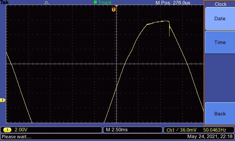
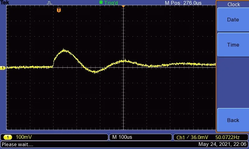
Visualised on an oscilloscope these switching spikes are somewhat obscured by the relative large 50 Hz heater voltage (Fig 1).
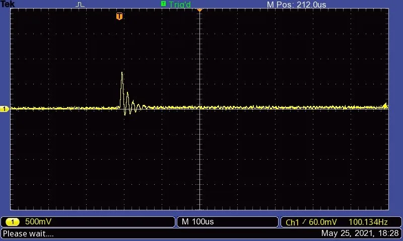
We have employed a technique used by Rod Elliot. to better see the switching spikes. The 50 Hz filament supply is removed by a high pass filter, leaving the switching spikes induced on the heater winding. Fig. 2 shows the switching spikes induced onto the heater winding with the stock 10 nF snubbing caps across the bridge rectifier diodes removed. What you can see is a relatively large initial spike (peak just under 2V, 500 mV / division verticle scale), followed by a damped train of oscillation, a phenomenon referred to as ringing. The very steep rise time indicates a significant high frequency content, which of course does not need much stray capacitance to couple into other windings etc (impedance of a capacitor goes down with frequency).
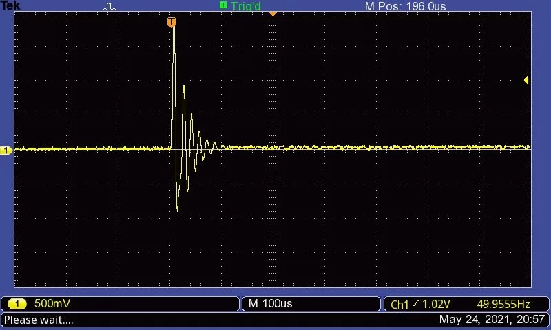
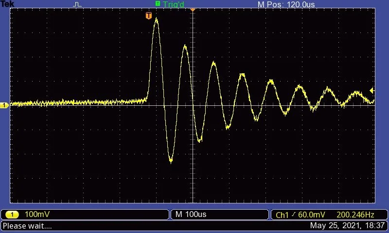
Fig. 3 shows the stock circuit which has 10 nF caps in parallel with the rectifier diode (C19, C20, C21 and C23 in schematic I have). These caps are included to reduce coupling of rectifiers switching spikes into the heaters by not only the magnitude of initial spike, but also the frequency of the subsequent ringing; lower frequencies will induce less noise into the heater winding and should be less insidious. The vertical scale is 100 mV / division (cf 500 mV / division with the unsnubbed rectifier), the first peak is about 380 mV and is not as steep as the unsnubbed ringing.
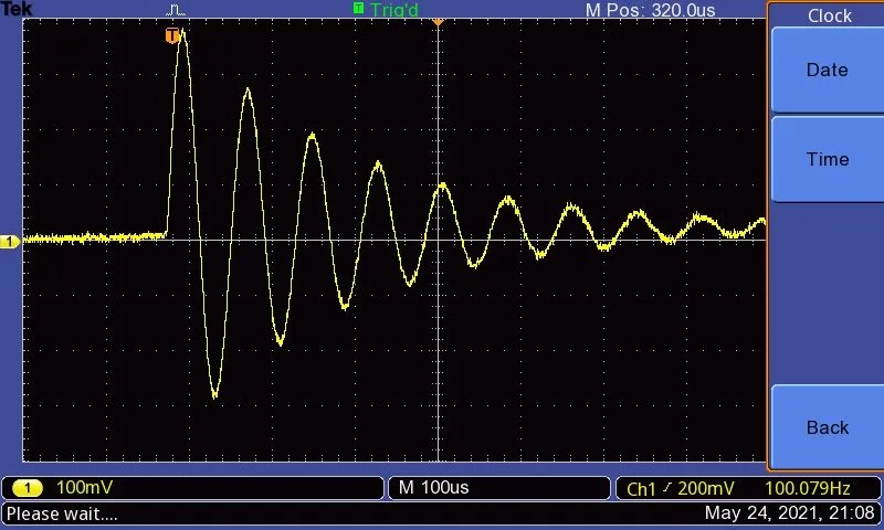
The extent of the ring is actually not surprising as we have added no resistance to the circuit to damp the resonance, we have simply altered the frequency of the resonance.
Another way to snub a rectifier is to add a Zobel network/s either across each rectifier diode, or across the HT secondary winding. A Zobel network is simply a capacitor and resistor in series, the resistor provide damping by converting the electrical energy in the circuit into heat (this is analagous to mechanical damping). For best results the capacitor and resistor values need to adjusted to the circuit they are being used in, and we tried a variety of values.
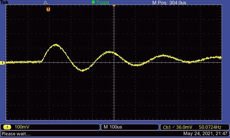
Fig 4 and 5 show results with 100nF / 10 ohm and 100 nF / 100 ohm networks. As we can see these are a massive improvement even on the stock snubber network with 100 nF / 100. Both networks show a lower initial peak. Note 100 mV / divison verticle scale.
Another option is to try some soft recovery diodes in the rectifier. We installed MUR1100 diodes instead of the stock 1N4007s. Fig 6 shows the MUR1100 diodes with no snubbing caps. This is a dramatic improvement on the stock diodes. Note this graph employs the same verticle scale as Fig 2.
We have added the snubbing caps back in, and get a similar result to the stock diodes; not surprising as the snubber capacitance swamps the diode capacitance (Fig. 7).
The 100 nF / 100 ohm diode Zobel network again gives pretty much the same results as with the stock diodes (not shown).
I have also tested some other capacitor and resistor values, and have managed to reduce the ringing at the expense of increasing the amplitude of the initial spike; I am not yet convinced that the 100 nF / 100 ohm option is optimal.
Two other areas that seem to improve noise are reducing the current draw of the power valves (these amps can be biased very hot), and using a hum balance pot on the filament supply.
We have now designed a replacement power valves PCB that incorporates a trim pot that can be adjusted to minimise hum.
Noise can still be a problem, and I guess part of this is due to the layout with unshielded PCB traces running to and from the first valve stages.
To be continued……..