Custom Footswitch for Fender Vibroking

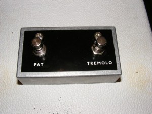
Here a picture of a custom footswitch we made for a Fender Vibroking.


Custom footswitch


The problem with the amp’s stock footswitch is that there are no LEDs on it to indicate which functions have been activated, so we built a footswitch with LED indicators for each feature. The LEDs can be powered either from a battery or an external 9V supply.

We have an in house engraver, which makes the switch look a lot more professional at little extra cost.

We also chose super bright red and blue LEDs, fortuitously as it happens as I subsequently found out the customer was one of 8% of men with red/green colour blindness.

Posted in Effects pedal, Pedal building | Comments closed

Boss Pedal Repair at JPF Amps London Workshop

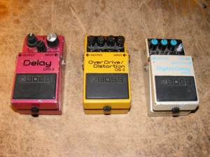
Here are 3 Boss pedals I’ve had in for repair at our workshop; a DM-2 analogue delay, an OS-2 overdrive /distortion pedal, and a DD-3 digital delay.


BossPedals


Boss pedals are, in my experience, very reliable. None of these pedals had major faults.

The DM-2 (which for the uber pedal geeks was the earlier MN3005 version), needed a new DC input connector.

The OS-2 had suffered from the wrong power supply being applied to it (probably AC), and needed both the op-amps replacing as well as the polarity protection diode and the first filter cap.

The DD-3 needed a new mode selector as the old on had suffered a gig injury.

Posted in Effects pedal, Effects repair, JPF Amps | Comments closed

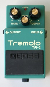
Boss TR-2 effects pedal repair and modification

As well as repairing guitar amplifiers, we also repair and modify effects pedals.

The Boss TR-2 is a good sounding tremolo pedal, but suffers from a loss of volume when the effect is engaged.

Boss TR-2

This is easily cured by changing R9 on the PCB from 10k to a lower value.

I find 6k8 works well.

This pedal also needed a new switch.


Posted in Effects pedal, Effects repair | Comments closed

New JPF Sound Sample and “Rockumentary”

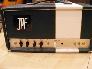
We now have a “rockumentary” on Youtube where I go into some detail about the design and construction of JPF amps, and there is also some footage of David PAge demonstrating the a SC15 combination.

These can be accessed via our media page.

Posted in Amp building, Guitar Amps, JPF Amps, Sir Charles | Comments closed

JPF Prototype Nimrod 100W Bass / Guitar Amplifier

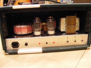
Here are some photos of the 1st prototype of a 100W bass / guitar amp.

The amp was initially designed as a bass amp (mainly for my use!), but there was some interest in the design from a couple of guitar players, so we will develop a guitar version of this amp too.

The amp fits into our standard head shell and will weigh in at a fairly manageable 14kg.

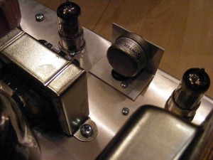
We have used the same pre-amp topology as used in our other amps, but with the addition of a defeatable active mid cut/ boost control. Like the control on Ampeg amps, this uses a tapped inductor to allow selection of 5 different frequencies to cut or boost.

This version on the amp uses 2 x KT88s to deliver 100W, but the next iteration of the design will be capable of using either KT88s or 6550s.

Anyhow, here are the photos.

Front (no control panel yet!)

Nimrodfront


Rear. 2 x KT88s

Nimrodback


Tapped inductor, custom wound by Sowter Audio Transformers. Mu metal screened for low hum.

NimrodInductor


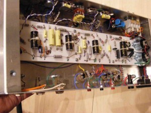
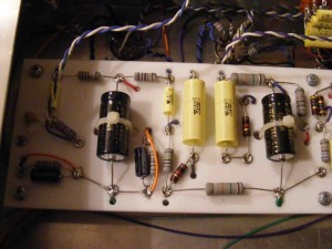
Gut shots showing the layout and wiring.


NimrodGutshot Nimrodboard

Posted in Amp building, Bass Amps, JPF Amps | Comments closed

Fender Blues Junior Guitar Amp Repair

I see quite a few Fender Blues Juniors in the workshop for repair; not that they are unusually unreliable, it’s just there are a lot of them out there!

However you do see many of the same faults occurring, so here’s some photos highlighting these from a recent repair.

Firstly, like many amps that use EL84s, the power valves are run very hot. This isn’t helped by Fender wiring their European export amps for 230 VACmains , rather than 240 VAC. This means that all the Fender amps sent to UK run on higher voltages than they should.

I always rewire any Fender amps I have in the workshop to UK voltage.

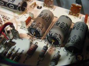
As you can see from the photo below (not my best effort with the camera) the filter caps in this amp had started to leak. This seems to be an unusually common problem on Fender amps from the mid nineties. Whether Fender got a bad batch of caps, I don’t know.

Regardless, Illinois Caps (IC) don’t have the best reputation, so if I need to change any of the filter caps I change all of them. I like to use German-made F&T caps for this.

FenderBJ5

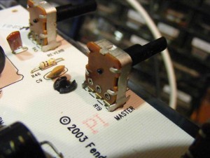
The pots get easily damaged on the Blues Junior. Often the tabs work loose on the back of the pots, so I always bend these back in with some pliers.

FenderBJ3


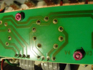
Finally the heat from the power valves often causes damage to the solder joints on the sockets for these valves.  There is also a dry joint on the ribbon cable from the main PCB. I resoldered all of these.

FenderBJ1

A pair of new valves and adjusting the lead dress to eliminate oscillation, another common problem with the Blues Junior and the amp was repaired.

Posted in Amp repair, Guitar Amps | Comments closed

Aguilar AG500 Bass Amp Repair: Man vs SMD Round 1

Here’s a repair I conducted on a more modern amp, a Aguilar AG500 bass guitar amplifier, where we were dealing with the dreaded SMDs.

This amp is quite an interesting design as it has a class D output stage, however unlike most class D amps it’s not ultra light. It employs a linear power supply (rather than the SMPS that is de rigueur in class D amps), and so has a large,  heavy mains transformer. It also doesn’t employ fan cooling, necessitating a relatively large heat sink.

Both these design decisions I think were made in the interests of reliability. Linear power supplies are generally more reliable than SMPS and can be easily repaired.

Relying on a fan for cooling means that the amp is imperiled by fan failure, a common problem in my experience.

Anyhow, the AG500 has 2 channels, and this one arrived in the workshop with one channel not working and the other have a very weak signal.

Injecting a signal into the power amp via the fx return showed that the power amp was working fine, so the problem was in the pre-amp.

A quick look inside the amp revealed a PCB populated with surface mount devices (SMDs), and it was obvious that the pre-amp was a relatively complex design (for a bass amp!).

Fortunately Aguilar were very helpful (unlike many manufacturers…..) and, after signing the requiste NDA, supplied me with a service manual for the amp.

As the pre-amps channels are cascaded, failure in the first channel would significantly reduce the signal in through the other channel, so it was likely that the faults were caused by component failure in channel one.

It soon became apparent that transistors Q1010 and Q1009 in the channelone had failed.
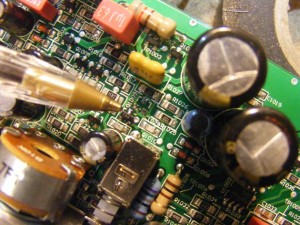
SMD1


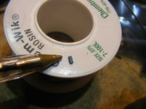
You can see where I’ve removed one of the offending items, with a biro in shot to give some idea of the scale of the problem. A steady hand is quite important in this type of repair.

Once these devices were replaced the amp worked fine; indeed it sounded very good.

Another snap of an SMD transistor & biro.
 

Smd3

Posted in Amp repair, Bass Amps, Guitar Amps | Comments closed

VOX Night Train Guitar Amplifier Repair

Here’s some photo’s from a recent repair of a VOX Night Train amplifier.

The amplifier was producing no sound.

Curiously the HT voltage on the first pre-amp valve was only 95 VDC, way below spec.

I removed the valves and the HT on the first valve stage was still only 95 VDC. On further investigation I found that there was only 10k of resistance from the HT to ground on the first valve, ie something was shorting to ground.

Finding the problem was an interesting exercise.

The filter cap was removed, tested and given a clean bill of health.

I then traced the HT circuit around the PCB, NOT helped by the brown gunge liberally spread over the board.

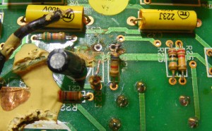
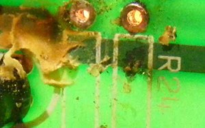
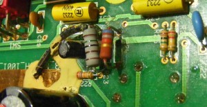
After mucho careful scraping I found resistors R23 and R24, which lie over a PCB track with HT on it.


VOXNT1


On lifting these resistors from the board, the resistance to ground was unmeasurable, and of further inspection, you could see that there was a short between R24 and the PCB track underneath.


VOXNT3


I replaced R23 and R24 with 1W MF resistors (all I had in the relevant values), and stood them off from the PCB trace to avoid any arcing/ shorting in future.

VOXNT2

Posted in Amp repair, Guitar Amps | Comments closed

Peavey Classic 30 Guitar Amplifier Repair

Here are some photos from the inside of a Peavey Classic 30 that I recently repaired.

The amp was brought in making a ton of crackling noises and was cutting out intermittently.

It had been looked at previously by someone who had concluded that the PCB had absorbed moisture (not possible), and had tried to cure this problem by removing the PCB and baking it for 5 hours! Suffice to say this didn’t cure the problem.

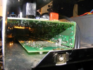
Anyhow, looking at the inside of the Classic 30 we can see why many techs don’t like working on them. The PCB snaps into 3 sections that are folded around, with the pots and jacks connected to the top panel and the valve sockets on the bottom.


PVC304


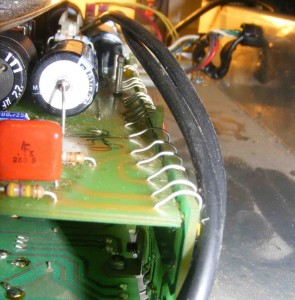
Worse the 3 sections are connected together with jumper wires.


PVC305

To change a component on the board requires that the board is removed from the chassis, and unfolded. Once the repair has been performed the PCB is refold around and inserted into the chassis. This is quite an involved process and each time you unfold the refold the PCB assembly you risk breaking the links or their solder joints.

Not a great design, although I expect this was the only way the amp can be as compact, and in their favour Peavey amps do seem to be pretty reliable.

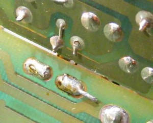
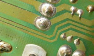
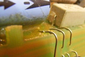
Anyhow, on removal of the PCB I found a couple of dry joints and a broken wire link.


PVC303

Dry Joint 1.

PVC302

Dry joint 2.

PVC301


Broken wire link.


I resoldered the joints , replaced the wire link and this cured the problems when the amp was reassembled.


Posted in Amp repair, Guitar Amps | Comments closed

More safety earthing issues. VOX AC30 and Yamaha PA

A couple of safety earthing issues I’ve seen over the last few weeks.

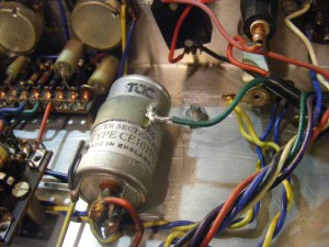
Here’s the safety earth from a recent repair on a JMI era VOX AC30.

Suffice to say, if you were going to solder the safety earth to something, then the chassis might have been a better bet……

AC30 earth

OK, that was a vintage amp with questionable earth bonding. Here’s the safety earth bond from a new Yamaha PA that had failed the PAT earth bond test.

The manufacturer had relied on the star washer piercing the powder coat on the chassis to give a good bond to earth.

Earth powder coat

The powder coat should have been masked off the power coating so there was bare metal under the earth bond to ensue a low earth resistance.

I scraped off the power coat before re-attaching the earth bond, and the amp passed the earth bond test.


Posted in Amp repair, Guitar Amps, JPF Amps, Vintage amps | Comments closed